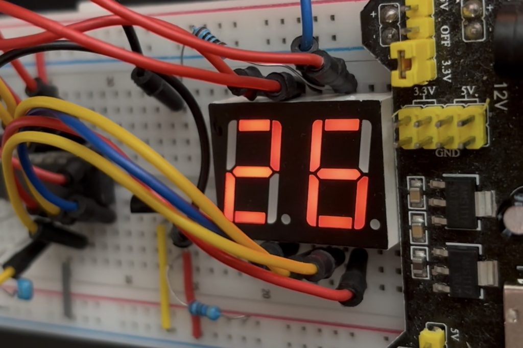
Hello, the much loved Seven Segment Digital Thermometer has been improved upon! This is version 2.0 of TINY Therm. It basically improves its brightness and by driving the display directly from the power rails using 2 transistors. I’ve also included a button so that it will stay asleep and only wake to show the temperature when pressed, then go back to sleep, conserving battery power. This will allow 3 AAA batteries to last for years without changing them! This is a nice bright display now so that it is much better than unlit lcds on the market that are hard to see from afar!
So let’s dive straight in. I’m going to emit most of what was spoken about in the previous post regarding this product. Instead I’m going to just dive straight in and give you the schematics, gerber and drill files to upload direct to JLCPCB.com, and the components Bill of materials list. I’ll also give you the assembly language code here too.
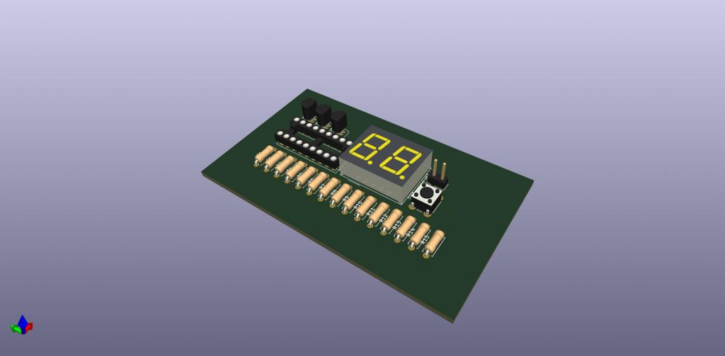
I’ll update here with a 3D Print file of a nice casing for it when I get the first prototype PCB’s back to populate myself and demo here.
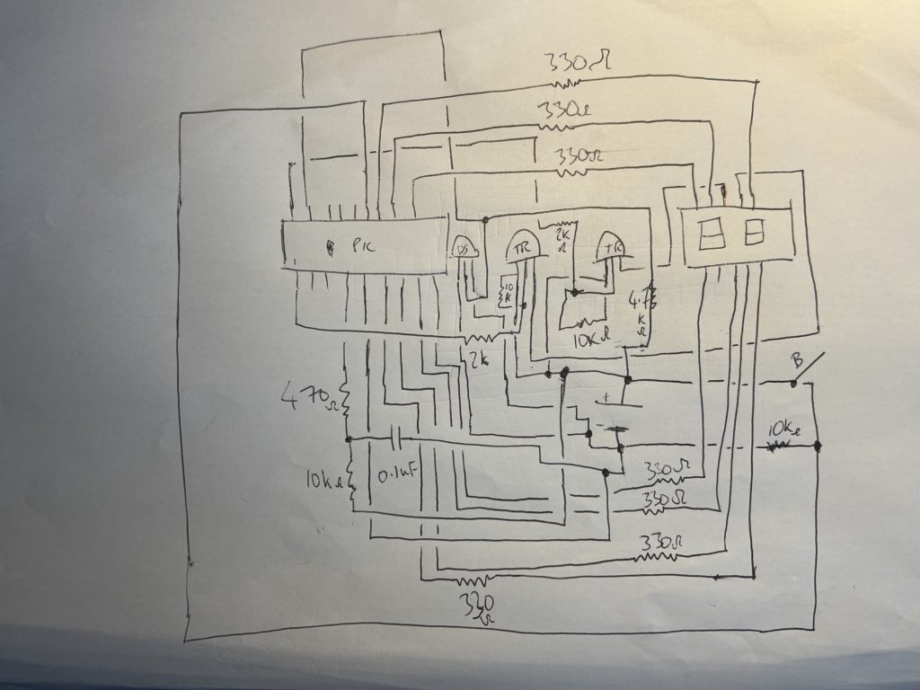
The schematic looks like this:
Components bill of materials list:
You can buy most of these from AliExpress, Amazon or eBay for pennies. Please support my blog by purchasing from these links below:
- PIC16F628 04/P (ensure its the 4 Mhz version, denoted by the 04/P)
- Dual 7 Segment Display (common anode). Not common cathode.
- DS18B20 (also on Amazon)
- 0.1uF ceramic capacitor, a few resistors per the schematic (bought in one assortment pack)
- New components for vs 2.0: 2 x 2N3906 transistors
Now, the assembly language code to flash the pic with can be seen here. I used MPLab 8.92 as that’s the latest version on windows that uses mpasm before they upgraded to MPLab X. I much prefer the old mpasm as it’s much simpler and usable for product design.
;**********************************************************************
;   This file is a basic code template for object module code         *
;   generation on the PIC16F628. This file contains the               *
;   basic code building blocks to build upon.  As a project minimum   *
;   the 16F628.lkr file will also be required for this file to        *
;   correctly build. The .lkr files are located in the MPLAB          *
;   directory.                                                        *
;                                                                     *
;   If interrupts are not used all code presented between the         *
;   code section "INT_VECTOR and code section "MAIN" can be removed.  *
;   In addition the variable assignments for 'w_temp' and             *
;   'status_temp' can be removed.                                     *
;                                                                     *
;   If interrupts are used, as in this template file, the 16F628.lkr  *
;   file will need to be modified. Refer to the readme.tmp file for   *
;   this information.                                                 *
;                                                                     *
;   Refer to the MPASM User's Guide for additional information on     *
;   features of the assembler and linker (Document DS33014F).         *
;                                                                     *
;   Refer to the respective PIC data sheet for additional            *
;   information on the instruction set.                               *
;                                                                     *
;   Template file built using MPLAB V4.00 with MPASM V2.20.12 and     *
;   MPLINK 1.20.10 as the language tools.                             *
;                                                                     *
;**********************************************************************
;                                                                     *
;    Filename:	    xxx.asm                                           *
;    Date:                                                            *
;    File Version:                                                    *
;                                                                     *
;    Author:                                                          *
;    Company:                                                         *
;                                                                     *
;                                                                     *
;**********************************************************************
;                                                                     *
;    Files required:                                                  *
;                                                                     *
;                                                                     *
;                                                                     *
;**********************************************************************
;                                                                     *
;    Notes:                                                           *
;                                                                     *
;                                                                     *
;                                                                     *
;                                                                     *
;**********************************************************************


	list      p=16f628            ; list directive to define processor
	#include <p16f628.inc>        ; processor specific variable definitions

	  __CONFIG	_CP_OFF&_BODEN_OFF&_PWRTE_ON&_WDT_OFF&_LVP_OFF&_MCLRE_OFF&_INTRC_OSC_NOCLKOUT
; PWRTE_ON enables power up timer delay ~72ms which should help screen to self initialise

; '__CONFIG' directive is used to embed configuration data within .asm file.
; The labels following the directive are located in the respective .inc file.
; See respective data sheet for additional information on configuration word.


;***** VARIABLE DEFINITIONS (examples)

; example of using Shared Uninitialized Data Section
INT_VAR       UDATA_SHR
w_temp        RES     1           ; variable used for context saving
status_temp   RES     1           ; variable used for context saving


; example of using Uninitialized Data Section
TEMP_VAR      UDATA      0x20     ; explicit address specified is not required
temp_count    RES     1           ; temporary variable (example)


; example of using Overlayed Uninitialized Data Section
; in this example both variables are assigned the same GPR location by linker
G_DATA        UDATA_OVR           ; explicit address can be specified
flag          RES     1           ; temporary variable (shared locations - G_DATA)

G_DATA        UDATA_OVR
count         RES     1           ; temporary variable (shared locations - G_DATA)


;**********************************************************************
RESET_VECTOR  CODE    0x000       ; processor reset vector

goto   start              ; go to beginning of program


INT_VECTOR   CODE    0x004        ; interrupt vector location
		goto INTERRUPT
MAIN        CODE


;===========================================================
; Lookup table (0 = ON, common anode)
;===========================================================
DigitToSeg
ADDWF PCL,F
RETLW b'00000001'   ; 0
RETLW b'01010111'   ; 1
RETLW b'01001000'   ; 2
RETLW b'01000100'   ; 3
RETLW b'00010110'   ; 4
RETLW b'00100100'   ; 5
RETLW b'00100000'   ; 6
RETLW b'01000111'   ; 7
RETLW b'00000000'   ; 8
RETLW b'00000110'   ; 9

INTERRUPT
retfie


LOOP		EQU	0X20	;DELAY LOOP
LOOP1		EQU	0X21	;DELAY LOOP
COUNT		EQU	0X22
O_BYTE		EQU	0X23
I_BYTE		EQU	0X24
FLAGS		EQU	0X25
CALC_CRC	EQU	0X26	;CALCULATED CRC
BCOUNT		EQU	0X27
TEMP1		EQU	0X28	;TEMP MEMORY DURING CALC_CRC
TEMP2		EQU	0X29	;TEMP MEMORY DURING CALC_CRC

;SCRATCHPAD IS READ INTO 0X2A - 0X32
TEMP_LSB	EQU	0X2A
TEMP_MSB	EQU	0X2B
TH		EQU	0X2C
TL		EQU	0X2D
RES1		EQU	0X2E
RES2		EQU	0X2F
C_REMAIN	EQU	0X30
C_PERC		EQU	0X31
CRC		EQU	0X32
UNITS		equ	0x38
TENS		equ	0x39


;pats variables
		count1 		equ 0x40	;used in delay routine
		counta 		equ 0x41	;used in delay routine
		countb 	equ 0x42		;used in delay routine
		SUBCHECK equ 0x43
		counter 	equ 0x44		;used in 2 digit display routine to switch between the two digits many times before exiting the loop so that the user can get some time to view the digits
        SEGIT equ 0x45
		SEGIT2 equ 0x46
		SAVEWR EQU 0X47
		FILE1 equ 0x48
		FILE2 equ 0x49
		FILE3 equ 0x50

		TENS_Split equ 0x51
        UNITS_Split equ 0x52
        TEMP equ 0x53
		CombinedByte equ 0x54
		LSB_Sanitise equ 0x55
		MSB_Sanitise equ 0x56
		temp equ 0x57
		TENS_AGAIN equ 0x58
		UNITS_AGAIN equ 0x59


;FLAGS BITS
PRESENCE	EQU	.0	;PRESENCE
DS_ERROR	EQU	.1	;CRC ERROR

;DS1820 BITS
DQ_BIT		EQU	0
#DEFINE		DQ	PORTA,DQ_BIT
#DEFINE		TRIS_DQ	TRISA,DQ_BIT


start		;Reset vector

	goto	START_OF_PROG

INITIALISE

movlw 0x07
movwf CMCON ; turn off comparitors so can use porta as digital i/o
	clrf	PORTB
	bsf	STATUS,RP0	; Change to bank 1
	movlw	b'00000000'	; Set PORTB as digital output
	movwf	TRISB		; Set data / control lines to Output
movlw b'00000000'
movwf TRISA ; Set PORTA as an output, but the DQ line will need to be both input and output at different times, which is toggled later in the program for the DS18B20 to communicate effectively
	bcf	STATUS,RP0	; Go back to bank 0

bsf PORTA, 0 ; Ensure RA0 high initially (bus idles high via pull-up) as per ChatGPT suggestion


;setting up the timer0 function for isr NO LONGER NEEDED AS USING PCL


	return


START_OF_PROG

	call	INITIALISE		; Set up port and screen

	nop		; not actually needed but gives me somewhere to RUN TO or insert BREAK

;	LCD_STRING	hello_world	; Use Macro to send string from lookup table to LCD

	nop		; not actually needed but gives me somewhere to RUN TO or insert BREAK

;	LCD_STRING	user_defs	; Define "graphics" characters

	nop		; not actually needed but gives me somewhere to RUN TO or insert BREAK


Gogo
	;call	convert
    ;movlw .25
    ;bcf STATUS, Z
    ;subwf TEMP_LSB, 1
    ;BTFSS	STATUS,Z
    ;call temp_low
    ;btfsc STATUS, Z
    ;call temp_high
    ;call display
BCF INTCON, GIE ; disable all interrupts
call READ_SCRATCHPAD
call SEGGY


	goto	Gogo


;*******************************************************************************************

READ_SCRATCHPAD
;READ SCRATCHPAD, CHECK PRESENCE & CRC
	BCF	FLAGS,DS_ERROR
	CALL	DS_RESET ;THIS IS THE INITIALIZATION ROUTINE
	BTFSS	FLAGS,PRESENCE
	RETURN			;NOT PRESENT

	MOVLW	0XCC		;SKIP ROM. THIS MEANS THE FOLLOWING COMMAND WILL ADDRESS ALL SLAVES ON THE LINE.
	CALL	OUT_BYTE
	MOVLW	0X44		;CONVERT TEMP
	CALL	OUT_BYTE

	CALL	PASSIVE_WAIT_CONVERSION ;WAITS WHILE DS18S20 CONVERTS TEMPERATURE A-D

;	CALL	WAIT_CONVERSION		;CAN BE LONG _ DO OTHER THINGS?

	CALL	DS_RESET
	BTFSS	FLAGS,PRESENCE
	RETURN			;NOT PRESENT

	MOVLW	0XCC		;SKIP ROM
	CALL	OUT_BYTE
	MOVLW	0XBE		;READ SCRATCHPAD
	CALL	OUT_BYTE

	CLRF	CALC_CRC
	MOVLW	TEMP_LSB	;ADDRESS TO STORE TEMP_LSB
	MOVWF	FSR
	MOVLW	.9		;READ 9 BYTES FROM SCRATCHPAD
	MOVWF	BCOUNT

NEXT_CODE
	CALL	IN_BYTE
	MOVWF	INDF
	MOVWF	TEMP1
	MOVLW	.8
	MOVWF	COUNT		;8 BITS PER BYTE
	INCF	FSR,F
	DECFSZ	BCOUNT,F
	GOTO	DO_CRC
	MOVF	TEMP1,W
	SUBWF	CALC_CRC,W	;Z WILL BE SET IF CRC CORRECT
	BTFSS	STATUS,Z
	BSF	FLAGS,DS_ERROR	;CRC WAS NOT CORRECT
	RETURN
DO_CRC
	MOVF	CALC_CRC,W
	XORWF	TEMP1,W
	MOVWF	TEMP2		;STORE IN TEMP LOCATION THAT CAN BE ROTATED INTO C
	RRF	TEMP1,F		;ROTATE DATA READY FOR NEXT BIT
	RRF	TEMP2,W
	BTFSS	STATUS,C
	GOTO	NO_CARRY
	MOVLW	0X18
	XORWF	CALC_CRC,F
NO_CARRY
	RRF	CALC_CRC,F
	DECFSZ	COUNT,F
	GOTO	DO_CRC
	GOTO	NEXT_CODE


;-----------------------------------------------------

DS_RESET
; RESET DS1820 _ CHECK FOR PRESENCE PULSE!
	BCF	FLAGS,PRESENCE
	CALL	PIN_LO
	MOVLW	.48
	CALL	DELAY_10US	;48 X 10US ~480US
	CALL	PIN_HI
	MOVLW	.6
	CALL	DELAY_10US	;6 X 10US ~60US
	BTFSS	DQ		;CHECK PRESENCE PULSE
	BSF	FLAGS,PRESENCE	;PRESENT
	MOVLW	.42
	CALL	DELAY_10US	;42 X 10US ~420US
	RETURN

;------------------------------------------------------

PIN_LO
	BCF	DQ		;SET DATA PIN LOW, DO ONCE INITIALLY ?
	BSF	STATUS,RP0	;SAFEST THIS WAY _ OTHER CODE MAY ACCIDENTLY CHANGE DQ?
	BCF	TRIS_DQ		;SET DATA PIN AS OUTPUT
	BCF	STATUS,RP0
	RETURN

;------------------------------------------------------
PIN_HI
	BSF	STATUS,RP0
	BSF	TRIS_DQ		;SET DATA AS INPUT WITH PULL UP!!!
	BCF	STATUS,RP0
	RETURN

;------------------------------------------------------
OUT_BYTE
	MOVWF	O_BYTE
	MOVLW	.8
	MOVWF	COUNT
OUT_BYTE_1
	RRF	O_BYTE,F
	BTFSS	STATUS,C
	GOTO	OUT_0
	GOTO	OUT_1
OUT_BYTE_2
	DECFSZ	COUNT,F
	GOTO	OUT_BYTE_1
	RETURN

OUT_0
	CALL	PIN_LO
	MOVLW	.6		;60US DELAY
	CALL	DELAY_10US
	CALL	PIN_HI
	GOTO	OUT_BYTE_2

OUT_1
	CALL	PIN_LO		;MOMENTARY _ LONGISH!
	CALL	PIN_HI
	MOVLW	.6		;60US DELAY
	CALL	DELAY_10US
	GOTO	OUT_BYTE_2

;------------------------------------------------------
IN_BYTE
	MOVLW	.8
	MOVWF	COUNT
	CLRF	I_BYTE
IN_BYTE_1
	CALL	PIN_LO		;3US
	NOP			;4US
	CALL	PIN_HI		;11US
	NOP			;12US
	BCF	STATUS,C	;13US
	BTFSC	DQ		;14US SAMPLE NEAR END OF 15US
	BSF	STATUS,C
	RRF	I_BYTE,F ;ROTATES IN THE CARRY BIT... EITHER 1 OR ZERO DEPENDING ON THE BTFSC DQ INSTRUCTION
	MOVLW	.4		;40US + EXTRAS _ MIN OF 45US
	CALL	DELAY_10US
	DECFSZ	COUNT,F
	GOTO	IN_BYTE_1
	MOVF	I_BYTE,W
	RETURN

;------------------------------------------------------
WAIT_CONVERSION
;WAIT END OF CONVERSION WHILE ACTIVELEY POWERED
	BCF	DQ		;SET DATA PIN LOW  ?? DO ONCE INITIALLY ??
	BSF	STATUS,RP0
	BCF	TRIS_DQ		;SET DATA PIN AS OUTPUT _ 0
	NOP			;1US
	BSF	TRIS_DQ		;SET AS DATA AS INPUT WITH PULL UP!!!
	BCF	STATUS,RP0	;3US
	GOTO	$+1		;5US
	GOTO	$+1		;7US
	GOTO	$+1		;9US
	GOTO	$+1		;11US
	GOTO	$+1		;13US
	BTFSC	DQ		;14US SAMPLE NEAR END OF 15US
	GOTO	CONV_FINISHED
	MOVLW	.6		;40US + EXTRAS _ MIN OF 45US
	CALL	DELAY_10US
	GOTO	WAIT_CONVERSION
CONV_FINISHED
	MOVLW	.4		;40US + EXTRAS _ MIN OF 45US
	CALL	DELAY_10US
	RETURN

;------------------------------------------------------
PASSIVE_WAIT_CONVERSION
;WAIT END OF CONVERSION WHILE PASSIVELEY POWERED
;ALSO WORKS WHILE POWERED
;MUST DRIVE DQ HIGH DURING CONVERSION

	BSF	DQ
	BSF	STATUS,RP0
	BCF	TRIS_DQ		;DRIVE HIGH
	BCF	STATUS,RP0

	MOVLW	.4		;4 * ~0.2S = ~800MS
	MOVWF	COUNT
	CALL	DELAY
	DECFSZ	COUNT,F
	GOTO	$-2

	BSF	STATUS,RP0
	BSF	TRIS_DQ		;FLOAT HIGH
	BCF	STATUS,RP0
	BCF	DQ
	RETURN

;------------------------------------------------------
DELAY
	CLRF	LOOP		; ~ 0.2S DELAY (~256 X 256 X 3 US)
	CLRF	LOOP1
ENCORE
	DECFSZ	LOOP,F
	GOTO	ENCORE
	DECFSZ	LOOP1,F
	GOTO	ENCORE
	RETURN

;------------------------------------------------------
DELAY_10US
	MOVWF	LOOP1
DELAY_10US_1
	NOP
	NOP
	NOP
	NOP
	NOP
	NOP
	NOP
	DECFSZ	LOOP1,F
	GOTO	DELAY_10US_1
	RETURN

;*******************************************************************************************


RE_READ
	CALL	READ_SCRATCHPAD
	BTFSS	FLAGS,PRESENCE
	GOTO	NOT_PRESENT
	BTFSC	FLAGS,DS_ERROR
	GOTO	READ_ERROR

	MOVF	TEMP_MSB,F
	BTFSS	STATUS,Z
	GOTO	NEGATIVE

	BCF	STATUS,C
	RRF	TEMP_LSB,F
				;TEMP_LSB IS DECIMAL TEMP
				;PLUS 0.5 DEGREE IF C SET
	return

NEGATIVE
	;2'S COMPLIMENT NEGATIVE ROUTINE

NOT_PRESENT
	;DS1820 NOT FOUND ROUTINE

READ_ERROR
	;READ ERROR ROUTINE

	GOTO	$		;TWIDDLE THUMBS.

convert
	movf	TEMP_LSB,w
    movwf	UNITS
	movlw	'0'

        movwf	TENS


DO10S
	movlw	.10
	subwf	UNITS,W
	btfss	STATUS,C
	goto	ADJUST
	movwf	UNITS
	incf	TENS,F
	goto	DO10S

ADJUST
	movlw	'0'
	addwf	UNITS,F
	return

SEGGY

		CALL GetBYTE
        CALL SplitToTens
        CALL DisplayDigits

;===========================================================
; Split number into tens and units
;===========================================================
; TEMP = input byte (0-99)
; TENS = tens digit
; UNITS = units digit

GetBYTE
movfw TEMP_LSB
movwf LSB_Sanitise
movfw TEMP_MSB
movwf MSB_Sanitise


; Inputs: byteA, byteB
; Output: byteC

; Step 1: Extract upper nibble of byteA to lower nibble
SWAPF LSB_Sanitise, W
ANDLW 0x0F ;mask the first 4 bits, just need the last 4 after the nibble swap above
MOVWF temp

; Step 2: Extract lower nibble of byteB to upper nibble
;movfw MSB_Sanitise, W
SWAPF MSB_Sanitise, W
ANDLW 0x70 ;mask last 5 bits just need the first 3 after the nibble swap above
MOVWF MSB_Sanitise


; Step 3: Combine
MOVFW MSB_Sanitise
IORWF temp, W
MOVWF CombinedByte ; combined the upper nibble ofr msb with the lower nibble
;of lsb to get msb_lsb like this


return

SplitToTens
;movlw b'00100001'
;movwf CombinedByte ;--- Test if 33 works for instance during split

; --- Start of conversion subroutine ---
CONVERT_TEN_UNIT:
    clrf        TENS_AGAIN      ; Initialize tens counter to zero
    movf        CombinedByte, W   ; Load the number to convert into WREG
    movwf       UNITS_AGAIN     ; Use UNITS_DIGIT as a temporary variable

LOOP_SUBTRACT_TEN:
    movlw       d'10'           ; Load 10 into WREG
    subwf       UNITS_AGAIN, F  ; Subtract 10 from UNITS_DIGIT
    btfss       STATUS, C       ; Skip the next instruction if C flag is set (no borrow)
    goto        END_LOOP_SUBTRACT ; Jump if borrow occurred (result is negative)
    incf        TENS_AGAIN, F   ; Increment the tens counter
    goto        LOOP_SUBTRACT_TEN ; Repeat the subtraction

END_LOOP_SUBTRACT:
    movlw       d'10'           ; Load 10 into WREG
    addwf       UNITS_AGAIN, F  ; Add 10 back to restore the remainder
    return                      ; Return from the subroutine
; --- End of conversion subroutine ---


;===========================================================
; Display both digits (multiplex) USING TRANSISTOR AS A ---- HIGH SIDE SWITCH -----. ie when io pin is high, display is off. I think the display has potentially switched digits in the wiring compared to the old one
;===========================================================
DisplayDigits:
movlw 0x1E
movwf FILE1

LOOPY1 movlw 0x03
movwf FILE2

LOOPY2 movlw 0x03
movwf FILE3

LOOPY3

   ;---- Tens (left) ----
        MOVF TENS_AGAIN,W
        CALL DigitToSeg
        MOVWF PORTB
        BSF PORTA,2          ; enable tens (RA2)
        BCF PORTA,1          ; disable units (RA1)
        Call Delayswitch
        ;BCF PORTA,2 old one to turn off tens
		BSF PORTA,1          ; turn off tens using new transistor


        ;---- Units (right) ----
        MOVF UNITS_AGAIN,W
        CALL DigitToSeg
        MOVWF PORTB
        BSF PORTA,1          ; enable units (RA1)
        BCF PORTA,2          ; disable tens (RA2)
        Call Delayswitch
        ;BCF PORTA,1          old one; turn off units
		BSF PORTA,2          ; turn off units using the transistor

decfsz FILE3, f
goto LOOPY3

decfsz FILE2, f
goto LOOPY2

decfsz FILE1, f
goto LOOPY1


goto carryon


Delayswitch	movlw	d'10'			;delay 250 ms (4 MHz clock)
	movwf	count1
d1	movlw	0xC7
	movwf	counta
	movlw	0x01
	movwf	countb
Delay_0
	decfsz	counta, f
	goto	$+2
	decfsz	countb, f
	goto	Delay_0

	decfsz	count1	,f
	goto	d1
	retlw	0x00


carryon
RETURN

END
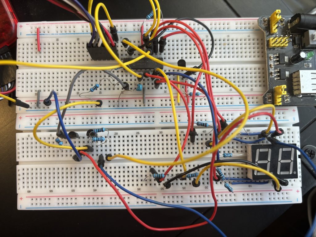
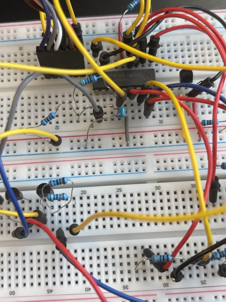
If you like, you can see the breadboard I used to prototype this for your reference:
And this was the original schematic I drew out first for your reference:
Now what you will need is the Gerber file to upload to JLCPCB. You may download it here:
All you do is go to https://jlcpcb.com, register for an account then hit “Order Now” at the top. Upload the Gerber file and leave all the other settings the same (i.e quantity 5, 2 layer, etc etc…) They will manufacture it for you and can send it to you within 10 days anywhere in the World for just £3 for 5 PCB’s, that’s 5 TINY-Therms, Bargain! All you’ll need to do then is solder the components onto the board, attach the battery pack of 3AAA batteries, then fire it up!
Enjoy!
Disclaimer Notice: This is an educational tutorial only and I will not accept any responsibility for damage or harm to property and/or persons as a result of you following and building this tutorial project. You are responsible for your own safety and performing any safety tests if used commercially. Ideally we recommend this for use only in personal/hobby projects.
This is an educational tutorial for personal use only. You must ensure you conduct the appropriate safety tests. But as an example, uses for this could include:
Industrial systems, consumer products, systems which are sensitive thermally, thermostatic controls, and thermometers, monitor various environments and machinery, power plants, and manufacturing, weather stations and home automation systems, measure temperature in solids, liquids or gases, Laboratories, Diagnostic labs, Dairy Industries, Domestic or industrial refrigerator temperature monitoring, baby thermometer, HVAC, automotive, research and quality control, adult thermometer, room temperature monitoring, outside temperature logger, industrial and consumer goods/products, wireless temperature monitor, LCD/LED screen thermometer, temperature logger, farming, agriculture, office, home, manufactured goods, electronics engineering, embedded systems, integrated products, digital products, physical products, projects, end products, consumer goods, pcb design, printed circuit boards, plastic enclosures, remote temperature monitoring, motors, surface plates, home appliances, computers, industrial equipment, warning electrical radiators, exhaust gas monitoring on cars, food production, 3d printed chocolates, alcohol breathalyser, transit, hvac, power and utilities, calibration instrumentation, heat exchangers, heating cooling systems, energy, red sensor, etc thermistor, rtd sensors,
PIC16F628 assembly PIC assembly language tutorial PIC microcontroller vs Arduino PIC vs ESP32 DS18B20 PIC code 1-Wire protocol PIC PIC16F628 thermometer project PIC assembly firmware PIC microcontroller efficiency Why use PIC microcontrollers
cycle-accurate timing deterministic microcontroller code low-level embedded programming bare-metal programming PIC 1-Wire timing accuracy microcontroller power consumption interrupt-driven temperature reading embedded systems optimisation minimal instruction cycles lightweight firmware design
Arduino overhead Arduino timing limitations ESP32 FreeRTOS overhead Arduino digitalWrite speed ESP32 latency issues microcontroller bloatware embedded systems performance comparison
“How to read a DS18B20 temperature sensor using PIC assembly” “Why PIC assembly is more efficient than Arduino” “PIC16F628 temperature sensor project with code” “Best microcontroller for simple temperature projects” “Cycle accurate 1-Wire code for PIC microcontrollers” “How to bit-bang 1-Wire in PIC assembly” “PIC16F628 DS18B20 wiring and schematic” “Minimalist microcontroller temperature monitor” “Bare metal programming vs Arduino libraries” “Why my Arduino DS18B20 readings are unstable” “Optimised DS18B20 firmware for 20 MHz PIC” “How to create a reliable digital thermometer without Arduino” “Understanding PIC assembly timing for sensors”
Domestic Purpose, Check the temperature of the water before bathing, to check the temperature of food items for cooking, to measure the temperature of grill stands, ovens, and other heating appliances.
Laboratory Purpose
To check the temperature of a solution.
To check the room temperature or atmospheric temperature to carry out experiments.
Industrial Purpose
To measure the temperature of the inner and outer surfaces of the walls.
Food industries use them to monitor the temperature of food items during various stages of preparation. Especially in the baking and cooking industries, they are very useful. By taking the right temperature, it is possible to achieve the desired temperature where the microorganisms do not multiply.
© Copywrite ODONO DESIGN 2023
DISCLAIMER
This is an untested project. This is for hobby and personal use only. We do not allow commercial use of this tutorial (ie selling it in an end product, but if you are making this for commercial purposes, YOU are responsible for all CE, FCC and safety testing according to your jurisdiction. We will not be held responsible for any fire, damage or injury caused by this project.
COPYRIGHT AND TERMS OF USAGE (LISCENSE)
You are free to use this file for personal, hobby or educational purposes only. No commercial use of this project is permitted. None of the content on this webpage (code and hardware designs) may be plagiarised to other websites. Failure to comply will result in legal action. Thank you.
This webpage is Copyright by Patrick O’Donoghue 2024. Temperature Monitor by Patrick O’Donoghue is licensed under CC BY-NC-ND 4.0